


.png)
.png) Français
Français .png) Deutsch
Deutsch .png) Italiano
Italiano .png) 日本語
日本語 .png) Português
Português  Español
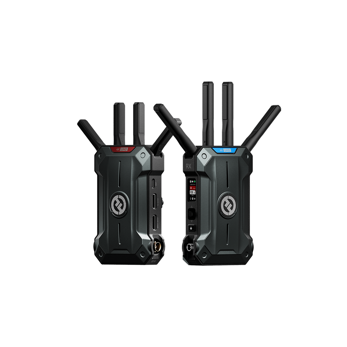
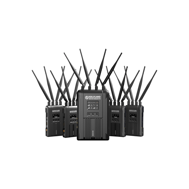
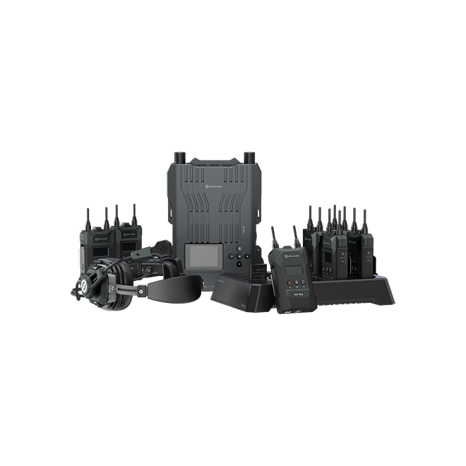
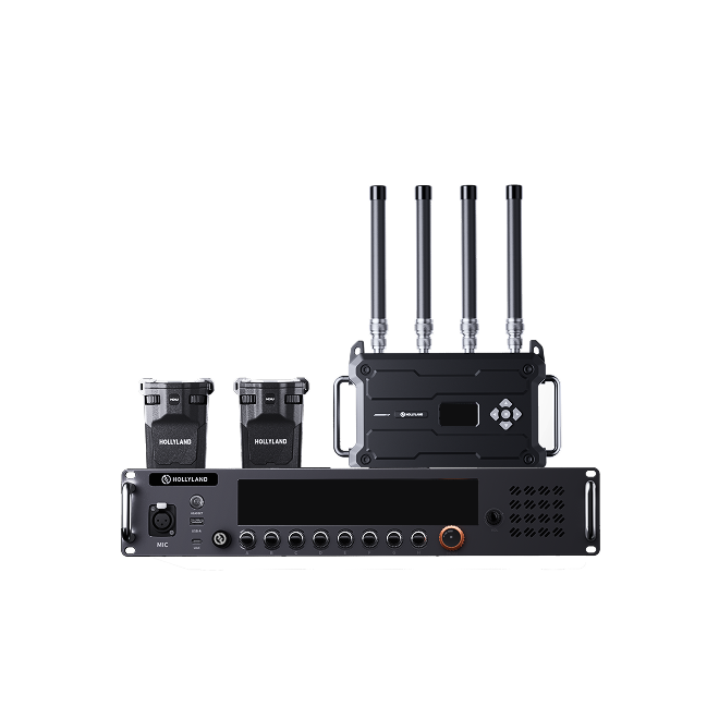
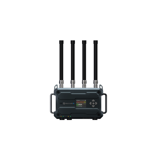
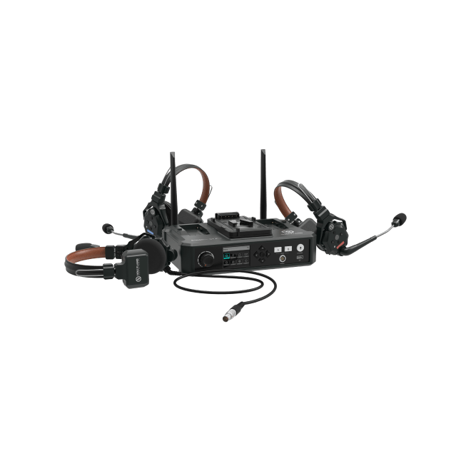
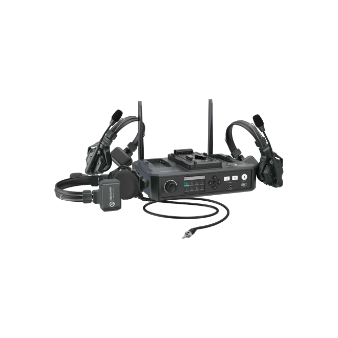
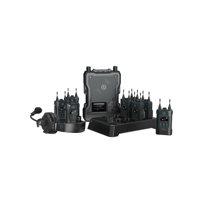
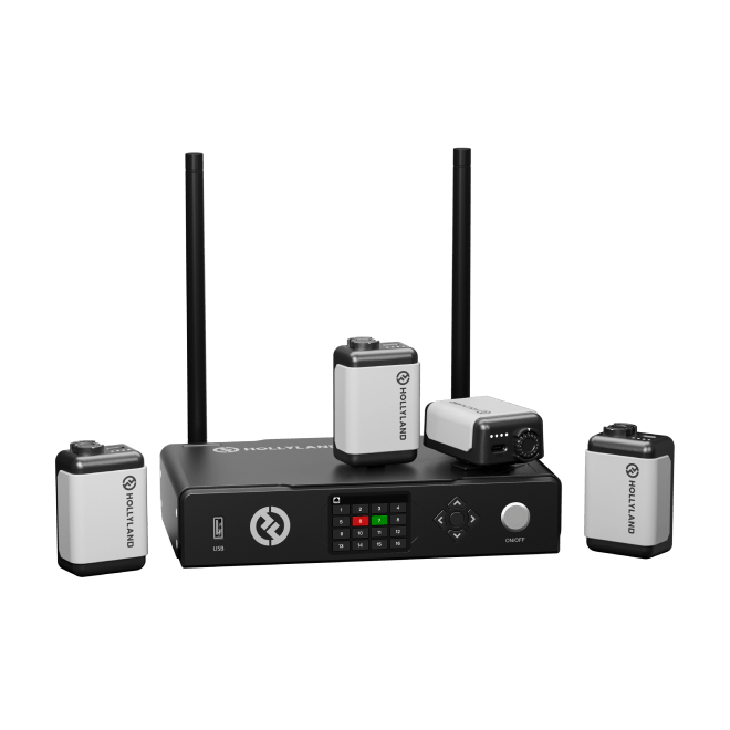
 Wireless Tally System Support

Regarding the pin order for the Tally unit’s DB interface, you need to disregard the traditional method of connecting the Tally unit to the switcher by matching each pin one-to-one. The specific connection method is as follows:
1. Connect the switcher’s GND pin to the Tally unit’s GND pin (Pin 25 or Pins 17 and 13).
2. Connect the Tally signal (PGM, PVW) transmission pins on the switcher to any pins on the Tally unit other than GND. You do not need to worry about the pin order; simply ensure that each pin is connected to the Tally unit’s DB interface.
3. Use the Tally unit’s DB Sequence Matching function to match the pin order with the switcher.
Note:
If there are not enough Tally signal ports, pins 13, 17 and 25 can also be used to receive Tally signals; simply ensure that one of these three pins is connected to the switcher’s DNG.